Guidelines and Practical Requirements for Selecting Fuses in New Energy Vehicles
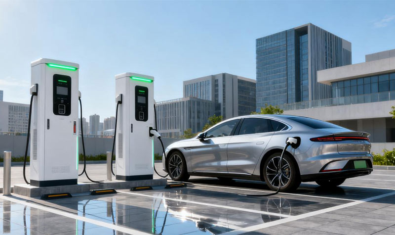
With the increasing penetration of new energy vehicles (BEV, PHEV, HEV), the safety and reliability of battery and electric drive systems have become a core industry concern. Within the protection system of the power battery and the vehicle's electrical system, the New Energy Vehicle fuse (EV Fuse) serves as the primary safety barrier. The rationality of its selection directly determines the protection efficiency during circuit faults, preventing risks such as battery thermal runaway and cable burnout. Integrating industry standards and practical vehicle application experience, this article provides a systematic reference for EV fuse selection, covering aspects such as application requirements, key parameters, and the selection process.
I. Special Requirements for Fuses in New Energy Vehicles (Distinct from Traditional Fuel Vehicles)
The unique characteristics of new energy vehicle electrical systems impose more stringent demands on fuses:
1.Wide Voltage Range Compatibility: Battery system operating voltages typically range from 300V to 1000V (reaching 1500V in some high-end models), far exceeding the 12V/24V low-voltage systems in traditional fuel vehicles. Fuses must withstand system peak voltages to prevent insulation breakdown.
2.Millisecond-Level Current Response: Due to low internal battery resistance (typically <50mΩ), fault currents can surge to several thousand amperes within 10ms during a short circuit. Fuses must possess both "rapid interruption" and "surge resistance" capabilities.
3.Complex Environment Endurance: Fuses must operate reliably in harsh conditions, including temperatures from -40°C (cold northern climates) to 125°C (engine bay/battery pack high temperatures), vibration frequencies of 10-2000Hz, and humidity up to 95% RH, without performance degradation.
4.Multi-Scenario Protection Coverage: Fuses must simultaneously protect the main power battery circuit, drive motor controller, onboard charger (OBC), DC fast-charging interface, air conditioning compressor, etc. Different scenarios require significantly different fuse characteristics.
Based on these requirements, the core functions of new energy vehicle fuses are defined as: interrupting fault currents within 10ms during short circuits, preventing component damage during overloads, and isolating faulty modules during failures—thereby establishing a comprehensive "Prevention-Protection-Isolation" safeguard chain.
II. Six Key Parameters for EV Fuse Selection (With Calculation Examples)
Selection must be based on the principle of "parameter alignment with actual operating conditions." The core parameters and practical requirements are as follows:
1. Rated Voltage
•Selection Principle: The fuse's rated voltage must be ≥ the system's maximum operating voltage (including peak charging voltage) to prevent arcing during interruption due to voltage mismatch.
•Example: For a battery system with a nominal voltage of 750V and a peak charging voltage of 850V, select a fuse with a rated voltage ≥ 850V (e.g., a DC 1000V specification).
•Industry Standards: Products must comply with IEC 60269 (for automotive DC fuses) and GB/T 13539 (Chinese standard for automotive fuses).
2. Rated Current
•Calculation Logic: Differentiate between "Continuous Normal Current" and "Scenarios Including Inrush Current":
•Normal Scenario (e.g., continuous battery discharge, OBC operation): Rated Current ≥ Continuous Operating Current × 1.25.
•Inrush Scenario (e.g., motor starting, fast-charging pulses): Rated Current ≥ Continuous Operating Current × 1.6 ~ 2.5 (to withstand 5-8 times instantaneous surge current).
•Example 1: A 100Ah battery pack has a continuous discharge current of 50A (normal scenario). The fuse rated current must be ≥ 50A × 1.25 = 62.5A (select a 63A specification).
•Example 2: A 150kW drive motor has a continuous operating current of 180A (with a starting surge of 900A). The fuse rated current must be ≥ 180A × 1.6 = 288A (select a 300A specification).
3. Breaking Capacity
•Core Requirement: The breaking capacity must be ≥ the maximum possible fault current in the circuit. Fuses in the main power battery circuit typically require a breaking capacity ≥ 50kA, while those in auxiliary systems require ≥ 10kA.
•Note: If the battery system's maximum short-circuit current is 45kA, select a fuse with a breaking capacity ≥ 50kA to prevent fuse rupture during interruption.
4. Time-Current Characteristic
•Balancing Need: Must avoid "nuisance tripping from instantaneous inrush" while ensuring "rapid interruption during faults":
•Motor Starting / Fast-Charging Scenarios: Must withstand 5-8 times the rated current for up to 100ms (e.g., a 100A fuse withstands a 500A surge for 100ms).
•Short-Circuit Fault Scenarios: Must interrupt 4-5 times the rated current within 10ms (e.g., a 300A fuse interrupts a 1200A current within ≤ 10ms).
5. Automotive Qualification
•Mandatory Certification: Products must comply with IEC 60269 (International) and GB/T 13539 (China) certifications.
III. Common Fuse Types for New Energy Vehicles and Their Scenario-Based Applications
The structural and performance differences among various fuse types determine their suitable application scenarios. The following section provides precise matching recommendations based on our official product models:
|
Fuse Types |
Core Strengths |
Application Scenarios |
Selection Examples |
Corresponding Official Model (Aite Fuse) |
|
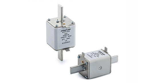
Bolt-Type Fuse |
Features secure installation and a high breaking capacity (≥50 kA) |
Main circuit of the power battery, Main circuit of the DC fast-charging system |
DC 1000V/300A (for 150kW vehicle models) |
ATEV-MM Series (DC 1000V/400A), ATEV-MF Series (DC 750V/300A) |
|
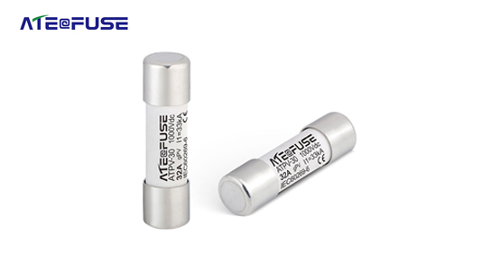
Cartridge Fuse |
Compact size and low cost |
Battery module-level protection, Auxiliary systems (e.g., air conditioning) |
DC 500V/30A (OBC auxiliary circuit) |
ATES-30L72 Series (DC 750V/250A) |
|
EV-Specific Fuse |
Wide temperature range, vibration resistance, and high reliability |
Drive motor controller, Charging interface, Main power circuit |
DC 750V/150A (for 100kW vehicle models) |
ATEV-MM Series (DC 1000V/150A), ATES Series (DC 750V/150A) |
Practical Selection Guidelines:
1.For the main power battery circuit, select the ATEV-MM Series (DC 1000V): Its breaking capacity reaches 50kA, it can withstand high temperatures up to 125°C, and is suitable for the main circuit in vehicle models with a power rating above 150kW.
2.For battery module protection, prioritize the ATEV-MD Series (DC 500V/100A): Its cylindrical bolt-type structure saves crucial space within the battery module.
3.For the fast-charging interface, specify the ATES-30L72 Series: Its DC 750V rated voltage covers fast-charging peak demands, and the 30kA breaking capacity effectively manages short-circuit risks during charging.
IV. Five-Step Selection Process for NEV Fuses (With Verification Points)
Step 1: Confirm System Voltage Parameters
•Data Collection: Gather battery nominal voltage, peak charging voltage, and maximum system operating voltage.
•Selection Verification: Fuse rated voltage ≥ System peak voltage (e.g., for an 850V peak → select ATEV-MM DC 1000V specification).
Step 2: Calculate Current Requirements
•Continuous Current: Calculate based on battery capacity (Ah) and motor power (kW) (e.g., 100Ah battery / 2C discharge rate → 200A continuous current).
•Inrush Current: Consider motor starting surge (5-8 times continuous current) and fast-charging pulse current (3-5 times continuous current).
•Determine Rated Current: For normal scenarios, multiply by 1.25 (e.g., 50A → select 63A, corresponding to ATEV-MD 63A). For inrush scenarios, multiply by 1.6~2.5 (e.g., 180A → select 300A, corresponding to ATEV-MF 300A).
Step 3: Verify Breaking Capacity
•Calculate Maximum Fault Current: Based on battery internal resistance (R) and system voltage (U) using I=U/R (e.g., 750V / 0.01Ω = 75kA).
•Selection Requirement: Fuse breaking capacity ≥ Maximum fault current (e.g., for 75kA → select ATEV-MM series model with 100kA breaking capacity).
Step 4: Match Time-Current Characteristics
•Test Verification: Simulate motor start (withstand 100ms at 5 times current) and fast-charging pulses (withstand 500ms at 3 times current) without nuisance tripping.
•Fault Test: Simulate short-circuit conditions (must reliably interrupt within 10ms at 4 times current).
Step 5: Confirm Automotive Qualification & Installation
•Certification Requirements: Ensure full IEC/GB certification (certification reports for each model are available on the official website).
•Installation Compatibility: Verify interface type (bolt/blade), dimensions (diameter/length) match the installation space, and contact resistance ≤ 5mΩ (to prevent overheating).
V. Seven Key Considerations for Fuse Selection (Avoiding Common Pitfalls)
1.Avoid Incorrect Rated Current (Too High/Low): An excessively high rating (e.g., selecting a 300A fuse for a 200A circuit) compromises protection, while too low a rating (e.g., a 150A fuse for a 200A circuit) leads to frequent, unnecessary blowing.
2.Implement Graded Protection Design: Utilize high-breaking-capacity fuses (≥50kA, e.g., ATEV-MM Series) for the main circuit and medium-breaking-capacity fuses (≥10kA, e.g., ATEV-MD Series ) at the module level, establishing a coordinated "main-backup" protection scheme.
3.Ensure Coordination with Other Components: The fuse's interrupting speed must be faster than the disconnection time of relays and circuit breakers to prevent relay damage during a fault.
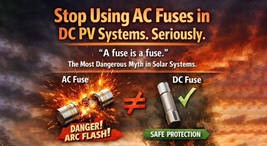
4.Do Not Mix Different Fuse Types: Never use low-voltage fuses intended for auxiliary systems in the main power battery circuit. Similarly, AC fuses (e.g., RT19 series) are strictly prohibited in DC circuits (like the main DC loop).
5.Select Installation Location to Mitigate Risk: Install fuses at least 10cm away from high-heat sources (e.g., exhaust pipes, engine blocks) and avoid damp areas (if mounted under the chassis, a waterproof cover is essential).
6.Consider Service Life and Maintenance: Automotive-grade fuses are designed for a service life of ≥ 8 years or 200,000 kilometers. Regularly inspect terminals for oxidation (replace the fuse if contact resistance exceeds specifications).
7.Reject Non-Standard Products: Fuses lacking proper certifications or with exaggerated specifications may fail during a fault, potentially leading to battery thermal runaway.
VI. Conclusion
Although fuses in new energy vehicles are considered "small components," they serve as a "critical line of defense" for electrical system safety. During selection, it is essential to move beyond the misconception of "focusing solely on parameters" and instead make comprehensive judgments by integrating vehicle-level voltage-current characteristics, environmental operating conditions, and protection logic—selections must not only comply with standards such as IEC 60269 and GB/T 13539 but also be validated through real-vehicle tests for high/low temperature, vibration, and short-circuit performance.
For automotive OEMs and component companies, prioritizing fuse brands with comprehensive automotive-grade certifications and proven adoption by mainstream NEV brands (such as AiteFuse) can significantly reduce post-market failure risks. Furthermore, with advancements in fast-charging technologies (e.g., 800V platforms) and larger battery capacities (e.g., 200Ah+), it is necessary to simultaneously upgrade fuse rated voltages (to 1500V) and breaking capacities (to 100kA+). The AT-EV-MM series available on our official website already incorporates such technical readiness and can meet the requirements of next-generation vehicle models.
Whether for pure electric, plug-in hybrid, or hybrid vehicles, scientific fuse selection and configuration remain vital to ensuring vehicle safety and enhancing user trust. To obtain precise model recommendations for specific scenarios, please visit our official website (www.aitefuse.com) to review detailed parameters of each series, or contact our technical team for customized solutions.